 ˹���á
˹���á �й��Թ�������
 �Թ���
�Թ��� ����ǡѺ���
 �Ըա�ê����Թ
 �Դ������
IT9121/IT9121E : ����ͧ�Ѵ��кѹ�֡��Ҿ�ѧ�ҹ俿��
�������Թ���
-
�����Թ���
IT9121/IT9121E
-
��Ҫ�
1,853 ����
������
ITECH
���
IT9121/IT9121E
-
�������ش�����
12/07/2017 11:32
-
��������´�Թ���

IT9121/IT9121E : ����ͧ�Ѵ��кѹ�֡��Ҿ�ѧ�ҹ俿��
The IT9121 power meter can provide the maximum input of 600 Vrms and 20 Arms and measurement bandwidth of 100 KHZ, and can be easily used for measuring the voltage, current, power, frequency, harmonics and other parameters. The only difference between IT9121 and IT9121E is harmonic measurement function. IT9121E doesn't have harmonic measurement function. The standard configuration includes USB, GPIB, RS232 and LAN communication interfaces and also interfaces for USB-based peripheral devices. Users can save the measured parameters into the external storage medium. The basic voltage and current accuracy is 0.1%. Moreover, the power meter has rich integrating functions, such as the active power. It is widely applied in test of motors, household appliances, UPS, etc. APPLICATIONS ▪ Power Supplies Tests ▪ Household Appliances Tests ▪ Energy Star ▪ Motor Tests ▪ Electronics ▪ Test Systems Features ▪ 4.3-inch color LCD (TFT) ▪ The row number of matrix displayed on the screen can be set freely and common measurement parameters can be displayed ▪ Input range: 600 Vrms / 20 Arms ▪ The voltage, current, power, harmonics and other parameters can be measured at the same time ▪ The accuracy of voltage and current measurement is up to 0.1% ▪ The power meter has a function of harmonic measurement, and can be used for measuring up to 50th harmonics ▪ The interfaces for USB-based peripheral devices are provided, and the user can save data into the external storage medium ▪ The power meter has rich and powerful integrating functions, and can be used for measuring electric energy which is bought or sold ▪ The power meter also has a function of frequency measurement ▪ Standard built-in USB, GPIB, RS232 and Ethernet communication interfaces Application ▪ Uninterruptible Power Supply (UPS) test ▪ Power supply test ▪ Appliances standby power consumption test ▪ Energy Star test ▪ Motor test ▪ Test system Application Advantages Power supply test Due to the features of small size,light and high efficiency, the switching power supplies are widely applied on nearly every kind of electronic device. To restricting the harmonic pollution to the grid caused by the switching power supply, it is necessary to do the relating test in research and production procedures to make sure that the switching power supplies can comply with the international standard. IT9121 and IT9121E are available to provide complete test solution for switching power supplies. 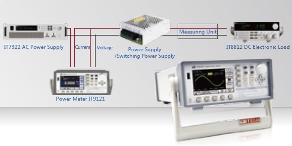
▪ Input voltage/current (RMS): Urms/ Irms ▪ Peak voltage Up-p/ Current Ip-p ▪ Active Power (W) ▪ Reactive power (VAR) ▪ Apparent power (VA) ▪ Maximum Voltage Upk+ and Minimum Voltage Upk- ▪ Maximum Current Ipk+ and Minimum Current Ipk- ▪ Crest factor (CF) ▪ Power factor (PF) Appliances standby power consumption test Each country has their own standard on standby power consumption of appliances. IT9121 power meter supports multiple measurements like power factor, harmonic, efficiency, power consumption and crest factor etc. Energy Star For external power supply products, the regulation--"Energy Star" can judge whether power supply models have high efficiency conversion either on AC/DC or AC/AC. With 5mA minimum scale range and 5 bits measurement display, IT9121 not only can accurately measure the standby current but also be able to figure out the power consumption which completely satisfies the “Energy Star” requirements. 1.1 and 2.0 version regulation of "Energy Star" external power supply by United States environmental protection agency 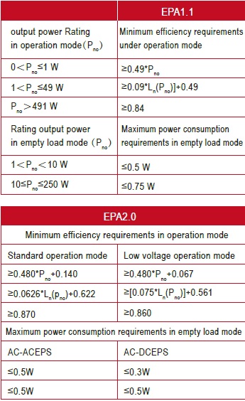
Motor test The speed control of industrial products uses PWM methods. IT9121 and IT9121E power meters are able to measure DC input signal with 0.5Hz-100 kHz bandwidth and input voltage up to 600V. The current can be supplied though an external transformer. 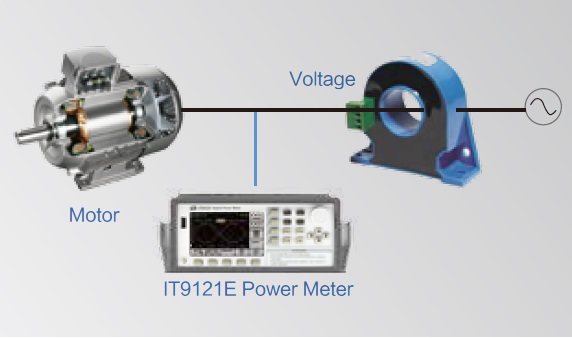
Harmonic Measurement The IT9121 power meter has a bandwidth of 100KHz, which can realize high-speed harmonic measurement within a wider dynamic range. In the harmonic mode, the voltage, the current, the active power, reactive power and phase of each harmonic and the factor of total harmonic distortion (THD) can be tested. In addition, IT9121 can be used for measurement of multiple harmonics, 50 harmonics of the fundamental frequency can be measured at most. The parameters of each harmonic measured by the IT9121 power analyzer can be displayed in the bar chart and the list, so 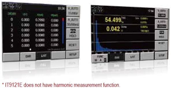
Rich Measurement Functions The IT9121 power meter can measure all AC and DC parameters, including the active power, reactive power, apparent power, power factor, voltage, current, frequency, phase difference, etc. It also has the function of integral measurement and up to 50th harmonic measurement, and can display single harmonic components. It is widely applied in tests of motors, household PCB, UPS, etc. Current Transducer Input The IT9121 & IT9121E power meter can be used for measuring the voltage of 0-600 V and current of 0-20 A. For measurement of the current above 20 A, the voltage input type current clamp or current transducer can be applied. When IT9121 is used, the user can select the range of 50 mV-2 V (EX1) or 2.5 V-10 V (EXT2). 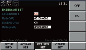
TFT High-resolution LCD IT9121 & IT9121E provides a 4.3-inch color high-resolution TFT LCD for the user, and real-time values can be displayed with high brightness and remarkable colors even in a dark test environment. In addition, the IT9121 power meter provides multiple interface display styles (View1,View4 and View12). The user can customize the screen display parameter type and display sequence, and roll over the screen display via the keys “Left” and “Right”. The humane design meets engineers’ measurement demands in different tests. 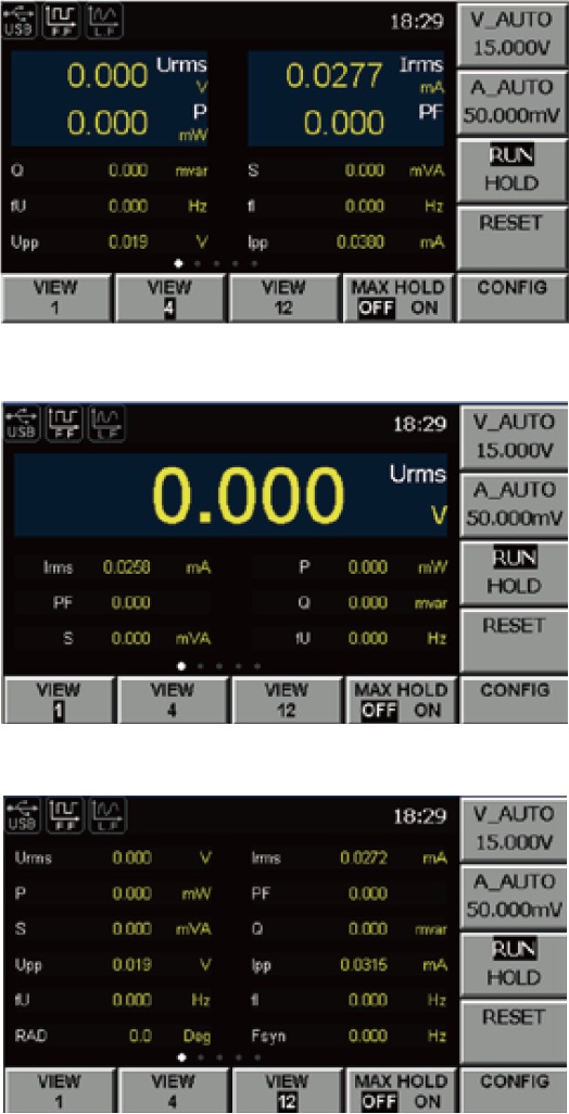
Oscilloscope function IT9121 & IT9121E power meter can display the waveform basing on sampling data.You can chose to display or hide the waveform of the input voltage and current. 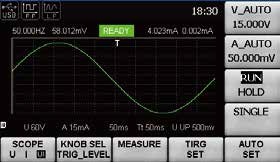
Integral Measurement Function Due to the power integral function, the sold/bought electric energy in the interconnected power grids can be measured. The IT9121 & IT9121E power analyzer can provide the current integral and active power integral (Wh). Automatic range switching and accurate integral measurement can be carried out in the Buy and Sell mode, according to the input level. 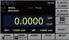
Optional accessory IT-E185 The testing fixture box(250V/15A) 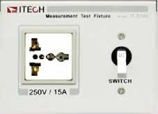
Built-in multi-interface In conventional test instrument, extra interfaces add cost. IT9121 & IT9121E provide multiple built-in interfaces including USB,GPIB,RS232 and Ethernet communication interfaces on rear panel. And the USB interface on the front panel can save data into external storage medium. Simplifying the configuration process and adding flexibility to change interface used without adding additional cost. 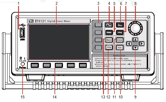
1 USB Interface 2. Display 3. Menu key 4. Waveform Display key 5 Basic functions 6. Harmonic key 7. Integrator key 8. Setting knob 9. Arrow keys 10. Hold/Esc key 11. Enter key 12. Image Save key 13. Parameter setting key 14. Menu key 15. Power switch 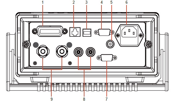
1. GPIB interface 2. Ethernet interface 3. USB Interface 4. RS232 interface 5. External synchronization signal interface 6. Power interface 7. External sensor interface 8. Voltage input terminal 9. Current input terminal Specification General Specification Model IT9121 & IT9121E AC input voltage 100 VAC — 240 VAC 50 / 60 Hz Warm-up time Apporx 30 minutes Operating
environmentTemperature : 5℃— 40℃ Humidity : 20% RH— 80% RH(No condensation) Altitude : 2000 m or less 2000 m Storage
environmentTemperature : -20℃— 50℃ Humidity : 20% RH— 80% RH(No condensation) Altitude : 2000 m or less 2000 m Installation Indoors Safety IEC 61010-1, EN 61010-1, Measurement CAT Ⅱ Maximum power
consumption50 VA Screen Display Detailed Information Display type Dimension:4.3-inch color LCD (TFT) Full screen pixel:480(horizontal)*272(vertical)points Waveform display pixel: 384(horizontal)*194(vertical)points Operating temperature: -20℃~ 70℃ Storage temperature: -30℃~ 80℃ Value display:matrix display Input Item Specifications Input terminal type voltage;plug-in terminal (safety terminal) Input type Current Direct input: large binding post External current sensor input DB9 connector Input type Voltage: Floating input through resistive voltage divider Current: Floating input through shunt Measure range Voltage: 15 V, 30 V, 60 V,150 V, 300 V, 600 V Current: Direct input: 5 mA, 10 mA, 20 mA, 50 mA, 100 mA, 200 mA, 0.5 A, 1 A, 2 A, 5 A, 10 A, 20 A Sensor input: EX1: 50 mV, 100 mV, 200 mV, 500 mV, 1 V, 2 V; EX2: 2.5 V, 5 V, 10 V Input impedance Voltage: Input resistance: Approx. 2 MΩ, input capacitace: Approx.13 pF (in parallel with the resistance) current: ▪ Direct input range 5 mA ~ 200 mA: Input resistance: Appro x 505 mΩ Input inductance: Appro x 0.1 μH ▪ Direct input range 0.5A ~ 20 A: Input resistance: Appro x 5 mΩ Input inductance: Appro x 0.1 μH ▪ Sensor input: Input resistance:Appro x 100 kΩ(2.5 V ~ 10 V) Input resistance:Appro x 20 kΩ(50 mV ~ 2 V) Continuous maximum
allowable inputVoltage: peak value of 1.5 kV or RMS value of 1 kV, whichever is less ▪ Direct input range 5 mA ~ 200 mA: peak value of 30 A or RMS value of 20 A, whichever is less ▪ Direct input range 0.5 A ~ 20 A: peak value of 100 A or RMS value of 30 A, whichever is less ▪ Sensor input : Peak value less than or equal to 5 times of the rated range Instantaneous maximum
allowable input (1s)Voltage: peak value of 2 kV or RMS value of 1.5 kV, whichever is less Instantaneous maximum
allowable input (1S)Current: ▪ Direct input range 5 mA ~ 200 mA: peak value of 30 A or RMS value of 20 A, whichever is less ▪ Direct input range 0.5 A ~ 20 A: peak value of 150A or RMS value of 40 A, whichever is less Sensor input : ▪ Peak value less than or equal to 10 times of the rated range Input bandwidth DC, 0.5 Hz ~ 1 MHz Continuous maximum
Common-mode voltage600 Vrms, CAT Ⅱ Line filter select OFF, cut off frequency of 500 Hz Frequency filter select OFF, cut off frequency of 500 Hz Range range of each unit can be set separately A/D converter Simultaneous conversion voltage an current inputs
Resolution: 18-bit
Maximum conversion rate: 10 μsVoltage And Current Accuracy Item Specifications Requirements temperature:23 ± 5℃ humidity:30~75% RH
Input waveform:
Sine wave crest factor: 3, common-mode voltage: 0 V
Number of displayed digits: 5 digits (6 digits when
including the decimal point)
Frequency filter : Turn on to measure voltage or current
of 200 Hz or 30 minutes after warm-up time has passed
After zero-level compensation or measurement range
is changedAccuracy DC: ± (0.1% of reading + 0.2% of range)
0.5 Hz ≤ f < 45 Hz:± (0.1 % of reading + 0.2 % of range)
45 Hz ≤ f ≤ 66 Hz:± (0.1 % of reading + 0.2 % of range)
66 Hz < f ≤ 1kHz:± (0.1 % of reading + 0.2 % of range)
1 kHz < f ≤ 10 kHz:± (0.1 % of reading + 0.2 % of range)
± (0.07 *f) % of reading + 0.3% of range)
10 kHz < f ≤ 100 kHz:
± (0.5 % of reading + 0.5 % of range) ± [{0.04x(f-10)}%
of readingActive Power Accuracy Item Specifications Requirements same as the conditions for voltage and current. Power factor:1 Accuracy DC: (0.1 % of reading + 0.2 % of range)
0.5 Hz ≤ f < 45 Hz:± (0.3 % of reading + 0.2 % of range)
45 Hz ≤ f ≤ 66 Hz:± (0.1 % of reading + 0.1 % of range)
66 Hz < f ≤ 1kHz:± (0.2 % of reading + 0.2 % of range)
1 kHz < f ≤ 10 kHz:
± (0.1 % of reading + 0.3 % of range) ± [{0.067x(f-1)}% of reading]
10 kHz < f ≤ 100 kHz:
± (0.5 % of reading + 0.5 % of range) ± [{0.09x(f-10)}%
of reading]Influence of power factor when power factor (λ)=0 (S:apparent power) ▪ ± 0.2 % of S for 45 Hz ≤ f ≤ 66 Hz ▪ ± {(0.2 + 0.2 × f) % of S } for up to 100 kHz as reference data f is frequency of input signal in kHz when 0 < λ < 1 (Φ: phase angle of the Voltage and current) (power reading )×[(power reading error%)+(power range %)× (power range/indicated apparent power value)+{tanΦ× (influence when λ=o)%}] When the line filter is
turned ON45 ~ 66 Hz: Add 0.3 % of reading < 45 Hz: Add 1 % of reading Temperature coefficient same as the temperature coefficient for voltage and current Accuracy when the
crest factor is set to 6accuracy obtained by doubling the measurement range
error for the accuracy when the crest factor is set to 3Accuracy of apparent
power Svoltage accuracy +current accuracy Accuracy of reactive
power Qaccuracy of apparent power + (√1.0004 - λ2) - (√1 - λ2)
×100 %Accuracy of power factor λ ± [(λ-λ/1.0002)+丨cosø-cos{ø+sin-1 (influence from the power factor when λ = 0%/100)}丨] ±1digit when voltage and current are at the measurement range rated input Accuracy of phase difference Φ ± [丨ø-cos-1(λ/1.0002)丨+sin-1(influence from the power factor when λ = 0 %/100)] ± 1digit when voltage and current are at the measurement range rated input Voltage, Current And Power Measurements Item Specifications Measurement method Digital sampling method Crest factor 3 or 6 Wiring system (one element model): single-phase , two-wire(1 P2 W) Range select select manual or auto ranging Auto range auto-range increase auto-range decline Harmonic Measurement Measured item All installed elements Method PLL synchronization method Frequency range Fundamental frequency of the PLL source is in the range of 10 Hz to 1.2 kHz PLL source Select voltage of current of each input element FFT data length 1024
 �Թ���
�Թ��� ��ǹ���Ŵᤵ����ͤ